Research Article
Lithium-Ion Batteries Cooling System Performance Improvement with Liquid and Phase Change Materials
- A. Mirmohammadi *
- Saeed Allahyari
Faculty of Mechanical Engineering, Shahid Rajaee Teacher Training University, Tehran, Iran.
*Corresponding Author: A. Mirmohammadi, Faculty of Mechanical Engineering, Shahid Rajaee Teacher Training University, Tehran, Iran.
Citation: A. Mirmohammadi, S. Allahyari (2024). Lithium-Ion batteries cooling system performance improvement with liquid and phase change materials. Scientific Research and Reports. BRS Publishers. 1(6); DOI: 10.59657/2996-8550.brs.24.030
Copyright: © 2024 Saeed Allahyari, this is an open-access article distributed under the terms of the Creative Commons Attribution License, which permits unrestricted use, distribution, and reproduction in any medium, provided the original author and source are credited.
Received: August 15, 2024 | Accepted: September 24, 2024 | Published: November 21, 2024
Abstract
Battery cooling is essential to prevent battery damage. Lithium-Ion batteries do not perform well at high temperatures; thus, by designing thermal management systems, the temperature of the batteries remains within the permissible range. In this paper, a Lithium-Ion battery is modeled electrically and thermally. The purpose is to investigate the temperature rise and the voltage drop of the battery and manage temperature rising by the cooling system. The results show that when the battery is discharged at a rate of 1c, the battery temperature reaches 318K and at a rate of 2c, the battery temperature reaches 335K which can cause damage. To overcome this problem, a cooling system is designed. In this system, temperature decreases to 303K for 0.01 m/s flow velocity in discharge rate of 2c. In addition, the battery cooling is investigated by using octadecane and nonadecane phase change materials. When octadecane and nonadecane are used, the battery temperature decreases to 308K and 310K, respectively. The results show that octadecane material has a better cooling performance for the battery.
Keywords: lithium-ion, battery, phase change material, cooling system
Introduction
Generally, reducing losses and increasing the efficiency of energy conversion are two main strategies for reducing vehicle fuel consumption. To reduce losses, researchers make efforts on factors such as losses due to aerodynamic drag, tire rolling resistance, and energy loss due to vehicle inertia; but recent studies show that the reduction in fuel consumption over a certain level just with a mechanical approach is not possible. Hence, in recent years, researchers have been attracted to use electricity in the automobile. There are many limitations such as the weakness of battery technology and its rapid depletion and low battery lifetime, and long charging time in using pure electric vehicles. Electrical energy use together with fossil energy has been a point of focus in hybrid cars (Ehsani et al 2007 [1]). Energy storage system that can ensure high mileage and high acceleration for the car is one of the essential issues in expanding clean energy vehicles. Various batteries, including lead, nickel, sodium, and lithium batteries have been proposed for use in electric vehicles (BuddeMeiwes et al 2013 [2]). Long life and low self-discharge rates are the best options for electric cars (Warner 2015 [3]).
In addition to the advantages for Lithium-Ion batteries, the disadvantages of, their high cost, limited-service life at high temperatures, low safety, and confine their performance of operating at high temperatures have prevented them from spreading widely in use (Conte 2006 [4]).
Recently, many attempts have been made to find the right material for electrodes for these types of batteries. Thermal management of Lithium-Ion batteries has a great impact on the efficiency, long lasting, and safety of these batteries. The proper operating temperature of Lithium-Ion batteries are between -20ºC to 60°C (Väyrynen et al 2012 [5]). Pasaran et al have proposed that a 15 to 35°C temperature range results in optimum performance of the battery (Pesaran et al 2013 [6]). Increasing the temperature beyond the stated range will drastically reduce the battery capacity. Mutlach et al., Showed that for each degree of temperature rise between 40 and 50°C there would be two months’ decrease for the battery life (Motloch et al 2002 [7]).
Mohammadian and Zhang have proposed a specific design for air-cooling by adding blades to the airflow channels. Using these blades, the maximum temperature was reduced and the temperature distribution became even more uniform (Mohammadian et al 2015 [8]). They have further investigated the thermal performance of the battery by incorporating porous metal foams into the airflow channels (Mohammadian et al 2015 and 2017 [9, 10]). Fan et al examined the effect of the battery distance on the battery pack and the effect of the input current rate on the efficiency of forced air-cooling. In addition, the effect of non-uniform distance of batteries on the battery pack has been investigated. Their results show that a 3 mm gap between the batteries and airflow with 40.8 m3/h is the best choice in this cooling method (Fan et al 2013 [11]).
Hugh et al have investigated a cooling system based on aluminum cooling plates. They have studied the effect of channel number, channel direction, and inlet flow rate at ambient temperature and discharge rate of 5C. It is found that the direction of the current is optimal when the current is flowing from the electrodes to the other parts of the battery. Because the heat generation does not occur uniformly in all parts of the battery and the heat generation is greater at the electrodes, the more current should pass through the electrodes, the temperature distribution becomes more uniform and the temperature difference at different points of the battery decreases. In addition, the higher the number of channels, the better the temperature distribution is achieved in the optimum value of 5 × 10⁻⁴ kg/s flow rate (Huo et al 2015 [12]).
Gonsrang and and Kasper have investigated a power management system (PMS) for an electric car equipped with a battery pack, super capacitor bank, and range extender. The proposed PMS deals with vehicular load distribution by solving a power management problem, formulated as a constrained quadratic program (CQP). Then, the optimized variables, such as the desired speed and optimized operation points of the car's components are implemented by controllers at a component level. Their results show that the proposed system optimally allocated an electric power load to the car components, without violating any physical constraints. Also, the comparative study showsthat the performance of the CQP in power management iscomparable to that of the benchmark, based on a nonlinear model predictive control (Gonsrang et al 2018 [13]).
Huanwei et al proposed an optimization design framework to minimize the maximum temperature difference (MTD) of automotive lithium battery pack. They have analyzed the cooling channels of two cooling and heat dissipation structures: serpentine cooling channel and U-shaped cooling channel. Also, they have proposed the adaptive ensemble of surrogate models based on an improved particle swarm optimization algorithm to support the optimization design of the serpentine cooling channel.
Their results show that the serpentine cooling channel has better cooling effect and the maximum temperature difference of the optimized scheme is reduced by 7.49% compared with the initial scheme, and the temperature field distribution of the lithium battery pack is more uniform (Huanwei et al 2021 [14]).
Zhang et al have proposed a novel hybrid battery thermal management system based on phase change material (PCM) and liquid cooling.In their proposed system, the operating temperature of the battery is mainly maintained by latent heat of PCM. In the case of thermal runaway condition, PCM acts as a heat buffer, and the heat dissipates through the liquid cooling system to avoid the thermal runaway propagation. Their results shows that the proposed system combines the advantages of PCM and liquid thermal management schemes, which can fully meet the heat dissipation demand under extreme operating conditions (Zhang et al 2020 [15]).
Fangxian et al have investigated the effect of flow rate on a phase change material nano-emulsion-based liquid cooling thermal management system for a lithium-ion battery pack. It has been found that latent heat is the main factor for enhancing the heat transfer rate when the flow rate of the coolant is low. However, when the flow rate of the coolant is higher than 200 mL·min-1, the main factor affecting the heat transfer rate is the disturbances of the nano-emusion particles (Fangxian et al 2020 [16]).
Rao et al have investigated the performance of thermal management systems of Lithium-Ion batteries by mini-channel cooling. Their model is a battery pack consisting of five batteries, and between the batteries is the cooling pan that flows through the channels. Their results show that as the number of channels increases, the maximum battery temperature decreases. It also decreases the maximum temperature with increasing discharge; but, increasing the channel width has little effect on temperature. Increasing the channel width from 3mm to 6mm also reduces the pressure drop by 55% (Qian et al 2016 [17]).
The use of an effective cooling system with high efficiency is among the approaches, which considered managing the batteries heating problem. Employing phase change materials (PCMs) can also manage heating problems. There are three heat management systems to keep the temperature within the permissible range, whichinclude:
1- Air cooling system
2- Water cooling system
3- Cooling system with phase change materials
The first two systems are classified as active systems. Phase-change cooling systems are inactive one. In the liquid cooling, heat is transferred with liquid through discrete tubing around each module with jacket around the module, by submerging modules in a dielectric fluid for direct contact. In the liquid cooling, heat is transferred through latent heat of phase change materials, so the pump or blower is not required. Hence, it is cost effective and simple in design and construction. In this paper, cooling system for decreasing the temperature of battery is designed and the effect of the flow rate of liquid and the efficiency of the phase change materials in decreasing the battery temperature is investigated. To improve the performance of the battery, in this research, the water is considered in liquid cooling and octadecane and nonadecaneinphase change material. Based on the authors’ knowledge, the effect of the octadecane and nonadecaneon battery cooling and their effects comparison with water have not been investigated in literature.
Battery modeling
The thermal behavior of the battery is essential because battery performance and battery safety are affected by the battery’s temperature. Laboratory methods have certain limitations in comparison to numerical simulation methods. An experiment, for example, designed for a particular environmental condition would take a long time. Also, laboratory methods cannot accurately measure the temperature at the battery center, and the temperature can only be obtained at the battery surface. Instead, numerical simulations do not have the limitations of laboratory methods and can easily monitor battery behavior under different conditions. It is assumed that the thermal properties of the battery including the thermal conductivity and the specific heat of the battery are temperature-independent to simplify the equations. In addition, it is assumed that the thermal properties of the battery are locally independent and are identical in all battery geometries. The first step in numerical simulation is the battery’s thermal modeling. The source term in the battery energy equation depends on the current and the voltage of the battery. Hence, the voltage and current intensity must be present for electric models. The voltage and intensity of the electric current can be obtained by using electrochemical and electrically equivalent circuit models.
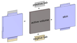
The energy and electrical coupled equations in the battery must be solved simultaneously by numerical methods to obtain the temperature, voltage, and current intensity. Figure 1 shows the modeled battery geometry. A Lithium-Ion battery with 35Ah capacity, 169mm wide, 179mm long, and 14mm thick is modeled. Electrical and thermal equations must be solved to obtain the temperature and voltage of the battery.
Figure 1: The geometry of the battery modeled in Ansys Fluent software
The governing equations
There are two electrochemical and electrical methods to obtain battery voltage. The electrochemical method based on the physics of the battery requires that the equations of charge transfer and mass transfer within the battery be solved by applying Ohm's law on electrodes and electrolyte for electric charge. Also Fick's law on electrodes and the solubility law in Electrolytes are obtained for mass transfer (Karimi et al 2012 and Li et al 2015 [18], [19]).
 (1)
(1)
 (2)
(2)
 (3)
(3)
 (4)
(4)

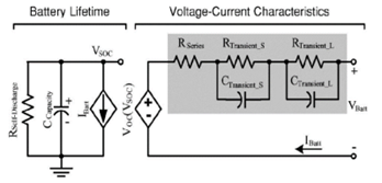
The battery behavior is analyzed in a circuit using capacitors and resistors to model the battery in the electrical method. In this paper, it is used the electrical equivalent circuit method proposed by Chen et al. (Yang et al 2015 [20]). In this method, the electrical parameters of the battery are obtained using one resistor and two resistor-capacitor pairs. Figure 2 shows the equivalent electrical circuit of this model.
Figure 2: The electric equivalent circuit of a Lithium-Ion battery
Boundary conditions
Heat can be dissipated from the battery by conduction, convection, and radiation methods. The heat is first transferred from the inside of the battery to its surface by conduction and then to the environment by convection and radiation (Chen et al 2006 [21]).
When thermal management systems are used in the battery, most of the energy from the battery surface is dissipated by convection and radiation, and conduction has very little effect. The boundary conditions are expressed as equation (5).
 (5)
(5)
The term I indicates the heat directed from the battery by convection and n shows the normal direction to the boundary plate. The term II represents the heat transfer by radiation. To simplify the calculations, heat dissipation by radiation can be written in the Newton's cooling law form. The radiation heat transfer coefficient is written as equation (6).
 (6)
(6)
Thus, the equation (5) written as equation (7).
 (7)
(7)
When the battery is cooled by connecting the battery to a solid object (for example, cooling with a blade or cooling with solid phase change materials), the heat is dissipated by conduction from the battery. The corresponding relationship is as equation (8)(Liu, 2017 [22]).
 (8)
(8)
The left opening of the battery domain is assigned as velocity inlet whereas the exit is treated as pressure outlet. The battery surfaces in the Tabs(positive and negative poles)are considered as wall condition. All surfaces inside the cooling system are considered as interior boundary condition.
Numerical simulation
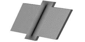
The finite volume method is used to obtain the battery temperature and voltage. Figure 3 shows the CFD mesh. Cubic mesh was generated in the ANSYS Fluent software. In the mesh quality skewness and orthogonal quality are 0 and 1 respectively. Aspect ratio and smoothness are 2.6 and 1.2 respectively in places where the temperature gradient is high. First, the values of the electrical parameters obtained by Chen et al are determined by voltage changes over time, then the energy equation is solved according to the voltage obtained and the transient temperature of the battery is obtained. Considering the high temperature in the transient solution of the battery, it is necessary to add a cooling system to the battery. At this point, the continuity and momentum equations are solved. The simulation was done in the ANSYS Fluent software. A 1-second time step is used to solve the equations transiently. The upwind scheme solver is applied to the discretized equations. Second order upwind solver was used and convergence criteria for the residuals of continuity and momentum equation were set as 10e-3 and 10e-6 for energy equation. The finite volume-based method solves the governing differential equations by integrating each control volume in the domain. The parameter temperature which is variable is interpolated between centers of the calculated domain. Inflow velocity and pressure outlet boundary conditions are considered. In the numerical solution, the boundary condition of the walls is considered to be insulated. The designed cooling channel material is aluminum.
Figure 3: Generated mesh for battery geometry
Mesh independency
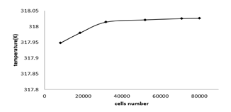
Figure 4 shows the battery temperature after fully discharging at the 1c discharge rate with the desired meshes. It is seen that after 70000 cells number the results indicate little difference. Therefore, we can conclude that the 70000 cells are sufficient for mesh independency.
Figure 4: Battery average temperature after 1c discharge rate with various cells number
Validation
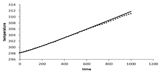
The validation of this paper has been performed using the experimental results of reference (Chen et al 2016 [23]). Figure 5 shows the numerical solutions results, are compared with the experimental at the 3c discharge rate. As can be seen, the simulation results are in agreement with the experimental and this indicates that the modeling performed can well predict the battery temperature.
Figure 5: Experimental and numerical solution results Comparison at 3c discharge rate
Results and discussion
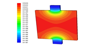
Electric current passes through the battery generate thermal energy and the higher the current intensity, the higher the heat generated. This increases the battery temperature. First, the battery is at ambient temperature that is 27°C (300.15K). Figure 6 shows the battery temperature contour at 1c discharge rate after 3600 seconds. As can be seen, at the active part of the battery, the electrodes and the electrolyte are located, the temperature is higher than the temperature of the battery tabs, because chemical reactions occur in the active part of the battery and the battery tabs only transmit electrical current.
Figure 6: Battery temperature contour at 1c discharge rate after 3600 second.
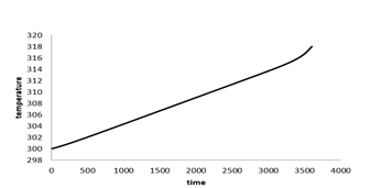
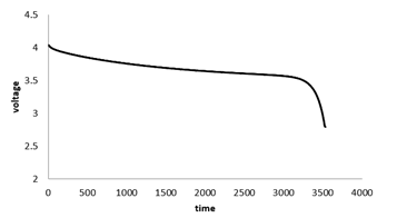
Figure 7 shows the Battery's average temperature changes over time at the 1c discharge rate. At 1c discharge rate after 3600 seconds the battery temperature reaches 318K, which indicates 18 degrees increase in temperature during the battery discharge. Figure 8 shows the battery's voltage changes over time. As shown, battery voltage reaches from 4.03 V at the start of discharge to 2.2V at the end of the discharge and the voltage drop is greater at the beginning and end of the battery discharge, due to the higher resistance to the transfer of lithium ions in the electrodes and the electrolyte.
Figure 7: Battery average temperature changes over time at 1c discharge rate
Figure 8: Voltage changes with time at 1c discharge rate
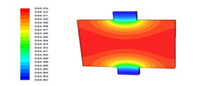
Figure 9 shows the battery's temperature contour at 2c discharge rate after 1800 seconds. As can be seen, in this case too at the active part of the battery, where the electrodes and the electrolyte are located, the temperature is higher than the temperature of the battery tabs, because chemical reactions occur in the active part of the battery and the battery tabs only transmit electrical current.
Figure 9: Battery temperature contour at 2c discharge rate after 1800 seconds
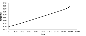
Figure 10 shows that the battery average temperature reaches to 335K when the discharge rate of the battery increases to 2c. The battery temperature more increases, because the current intensity increases.
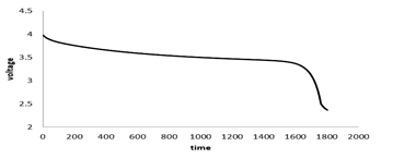
Figure 11 shows the battery voltage variations overtime at 2c discharge rates. It can be seen the battery discharges at a faster rate in 2c discharge rate. This is because of the electric current intensity more increases, and as time passes, more lithium ions move from the negative electrode to the positive electrode, and the battery is discharged faster. Due to the higher sensitivity of Lithium-Ion batteries to the operating temperature of the battery, battery temperature should be kept within the permissible range by careful use of thermal management systems. Because the battery temperature should not exceed the permissible limit in order to prevent battery life-shortening as well as optimum battery performance during discharge. In order to lower the battery temperature to avoid damaging the battery, one should use one of the cooling methods. In this paper liquid and phase change cooling methods are designed and simulated for its performance analysis.
Figure 10: Battery average temperature changes over time at 2c discharge rate
Figure 11: Battery voltage changes over time at 2c discharge rate
Battery cooling with water
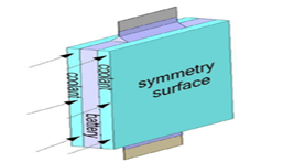
In another part, the cooling part of the battery is designed to lower the battery temperature and prevent damage to the battery. Figure 12 shows the geometry of the cooling part.
The battery cooling system with water was designed to allow water to pass through two channels on both sides of the battery. When the temperature of the battery exceeds the permitted range, a series of chemical reactions occur inside the battery. These causes damage the battery. To prevent this from happening, the battery temperature must be lowered by one of the cooling methods. Substances in the cooling part of the battery absorb the energy of the battery to reduce its temperature. The higher the inlet water velocity in the cooling part, the better the cooling performance, but this will be in return for the increased cost of running the water.
Figure 12: The battery water cooling part geometry used in the simulation
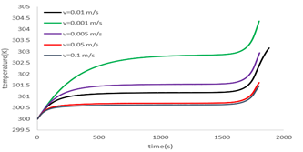
As shown in Figure 13, water flow at a rate of 0.01 m/s, which is water at an ambient temperature of 27°C, reduces the battery temperature at the end of discharge from 335Kin the absence of cooling to 303Kin the case where there is cooling (as shown in the figure 10 temperature of the battery without cooling is 335K at the end of discharge). In this case, the battery drains at a discharge rate of 2c. The effect of cooling was also investigated at different speeds, and as shown in Fig. 13, the best cooling mode was obtained at 0.1 m/s. The speed increasing above this value has little effect on cooling and results in inefficient use of energy for the pump.
Figure 13: Battery temperature changes at 2c discharge rate and different inlet velocity
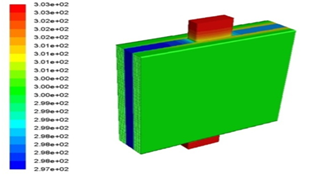
Figure 14: Battery temperature contour after cooling with water in 1800 sec at 2c discharge rate
Figure 14 shows how the battery temperature changes throughout the battery geometry after 3600 seconds. As the water flows through, the battery temperature rises just to 301K, while in the previous section where no cooling was added, the battery temperature rises to 335K. The flow of water through a channel exchange heat and decrease the battery temperature.
Battery cooling with phase change materials
Thermal energy can be stored in materials in both sensible and latent heat. The amount of sensible energy stored in the matter is a function of temperature, specific heat capacity, and amount of matter. The storage of heat energy by the material takes place latent as the phase changes from solid to liquid, liquid to gas and solid to gas. This research uses two octadecane and nonadecane phase change materials that changed from solid to liquid. These materials store the energy-evolving phase in steady melting and are converted to liquid at constant temperature by absorption of heat from the solid phase. Table 1 summarizes the multimodal properties of the phase change materials: octadecane and nonadecane.
Table 1: Properties of the phase change materials
| Material | Octadecane | Nonadecane |
| Melting point(ºC) | 28 | 32 |
| Latent heat | 244 | 222 |
| Thermal conductivity | 0.21 | 0.21 |
| Density | 814 | 782 |
| Specific heat | 1.90 | 1.91 |
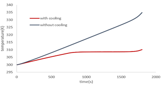
Figure 15 shows the battery temperature at the 2c discharge rate with the octadecane phase change in comparison to without cooling. In this case, there is an increase in temperature at the beginning and end of the discharge time, and at other times the temperature is almost constant. The increase in temperature at the beginning of the battery discharge is due to the fact that the heat generated inside the battery raises the temperature but the phase change material does not reach its melting point and has no effect on battery cooling. As the temperature reaches the melting point of the phase change material, it melts, and by storing heat generated inside the battery, it keeps the battery temperature constant. At the end of the battery discharge, the cooling ability of the system decreases, and the temperature rises as the phase-change materials are melted near the battery and their temperatures can melt beyond the point temperature.
Figure 15: Battery temperature at 2c discharge rate with octadecane phase change in comparison to without cooling
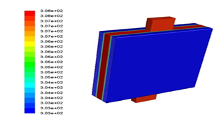
Figure 16 shows the battery temperature contour with octadecane phase change after 3600 seconds of battery discharge. It can be seen that after fully discharging, the battery temperature reached 308K, which allowed the battery to perform well.
Figure 16: Battery temperature contour with octadecane phase change after 3600 seconds of battery discharge
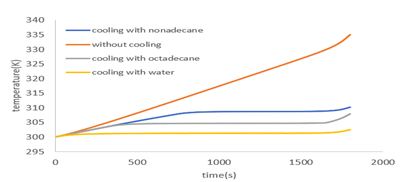
Figure 17 shows the battery temperature at the discharge rate of 2c with the water, octadecane and nonadecane in comparison to each other. As shown in the figure, water cooling has the best cooling performance between these cooling materials. The melting point of nonadecane is higher than the octadecane melting point, which is why it melts later than octadecane, resulting in higher battery temperatures and lower system cooling ability. The battery reached 310K when cooled with nanodecane after 1800 seconds that it fully discharged. This is 2 degrees higher than the octade can cooling. Therefore, in addition to the thermal properties of the phase change material, the melting point of these materials should also be considered. The closer the melting point of the phase change material to the battery temperature during heat generation, it is better for battery cooling.
Battery average temperature at 2c discharge rate with different cooling materials
Table 2 compares the results of cooling with liquid water and phase change materials. The lowest maximum battery temperature is obtained when using water cooling, which indicates a better performance of this coolant. The results show that the advantage of cooling with liquid water is that by increasing the speed and decreasing the inlet water temperature, the battery temperature can always be lowered but more energy needs to be consumed in pump. Also, the advantage of the phase change materials is that there is no need for energy, but cooling can be done to a limited extent and after the whole phase changeover has melted, the phase changeover has no effect on the cooling.
Table 2: Comparison of battery cooling materials
| the maximum battery temperature reached | Material used for cooling |
| 301K | Water |
| 308K | Octadecane |
| 310K | Nonadecane |
Conclusion
The simulation results show that:
- When the battery is discharged at a discharge rate of 1c, the battery temperature reaches 318K and at a discharge rate of 2c at 335K, which reduces both the optimum performance and the battery life. Also, may cause permanent damage to the battery.
- By designing a cooling part for the battery, the performance of the battery as measured. First by-passing water flow at a velocity of 0.01-0.1 m/s at 27°C, it reduces the battery temperature optimally to 301K at flow velocity in 0.1 m/s and keeps the battery temperature within the permissible range.
- The battery cooling was investigated using octadecane and nonadecane phase change materials, and the battery temperature reached 308K when using octadecane and 310K when using nonadecane. The results showed that the use of octadecane material resulted in better cooling of the battery.
- The advantage of cooling with liquid water is that by increasing the speed and decreasing the inlet water temperature, the battery temperature can always be lowered but more energy needs to be consumed in pump.
- The advantage of the phase change materials is that there is no need for energy, but cooling can be done to a limited extent and after the whole phase changeover has melted, the phase changeover has no effect on the cooling.
References
- Ehsani, M., Y. GAO, and j.M. Miller, (2007). Hybrid Electric Vehicles: Architecture and Motor Drives. Proceedings of the IEEE., 95(4).
Publisher | Google Scholor - BuddeMeiwes H., J. Drillkens, B. Lunz, J. Muennix, S. Rothgang and J. Kowal, (2013). A review of current automotive battery technology and future prospects. ProcInstMechEng, Part D J AutomobEng., 227:761.
Publisher | Google Scholor - Warner J., (2015). The Handbook of Lithium-Ion Battery Pack Design. Elsevier., 1–8.
Publisher | Google Scholor - Conte, F.V., (2006). Battery and battery management for hybrid electric vehicles: a review. E I Elektrotechnik Und Informationstechnik.,123:424–431.
Publisher | Google Scholor - Väyrynen, A. and J. Salminen (2012). Lithium-ion battery production. Journal of Chemical Thermodynamics, 46:80–85.
Publisher | Google Scholor - Pesaran, A. and G.K. Santhanagopalan, (2013). Addressing the impact of temperatureextremeson large format Li-ion batteries for vehicle applications. In 30th international battery seminar.
Publisher | Google Scholor - Motloch, C.G., J.P. Christophersen, J.R. Belt, R.B., Wright, G.L. Hunt and R.A. Sutula (2002). High-power battery testing procedures and analytical methodologies for HEV’s. Future Car Congress., 1–7.
Publisher | Google Scholor - Mohammadian, S.K., Y. Zhang, (2015). Thermal management optimization of an air-cooled Li-ion battery module using pin-fin heat sinks for hybrid electric vehicles. J Power Sources., 273:431–439.
Publisher | Google Scholor - Mohammadian, S.K., S.M. Rassoulinejad Mousavi, and Y. Zhang (2015). Thermal management improvement of an air-cooled high-power Lithium-Ion battery by embedding metal foam. J Power Sources., 296:305–313.
Publisher | Google Scholor - Mohammadian, S.K. and Y. Zhang, (2017). Cumulative effects of using pin fin heat sink and porous metal foam on thermal management of Lithium-Ion batteries. Applied Thermal Engineering., 118:375–384.
Publisher | Google Scholor - Fan L., J.M. Khodadadi and A. Pesaran, (2013). A parametric study on thermal management of an air-cooled Lithium-Ion battery module for plug-in hybrid electric vehicles. J Power Sources., 238:301–312.
Publisher | Google Scholor - Huo, Y., Z. Rao, X. Liu and J. Zhao, (2015). Investigation of power battery thermal management by using mini-channel cold plate. Energy Conversion Management., 89:387–395.
Publisher | Google Scholor - Gonsrang S. and R. Kasper, (2018). Optimization-Based Power Management System for an Electric Vehicle with a Hybrid Energy Storage System. International Journal of Automotive and Mechanical Engineering., 5729-5747.
Publisher | Google Scholor - Huanwei Xu and X. Zhang (2021). Optimization of liquid cooling and heat dissipation system of lithium-ion battery packs of automobile. Case Studies in Thermal Engineering101012.
Publisher | Google Scholor - Zhang W. and L.Zhicheng, (2020). Avoiding thermal runawayof lithium-ion battery modules by using hybrid phase change material andliquid cooling. Applied Thermal Engineering 116380.
Publisher | Google Scholor - Fangxian W. and J. Cao, (2020). Experimental and simulative investigationson a phase change material nanoemulsion-based liquid cooling thermal management system for a lithium-ion battery pack. Energy 118215.
Publisher | Google Scholor - Qian, Z., Y. Li, and Z. Rao, (2016). Thermal performance of Lithium-Ion battery thermal management system by using mini-channel cooling. Energy Conversion and Management, Elsevier., 126; 622–631.
Publisher | Google Scholor - Karimi, G. and X. Li, (2012). Thermal management of Lithium-Ion batteries for electric vehicles. International Journal of Energy Research., 37:13–24.
Publisher | Google Scholor - Li, G. and S. Li, (2015). Physics-based CFD simulation of a Lithium-Ion battery under the FUDS driving cycle. ECS Trans., 64 (33);1–14.
Publisher | Google Scholor - Yang, N., X. Zhang, G. Li and D. Hua, (2015). Assessment of the forced air-cooling performance for cylindrical Lithium-Ion battery packs: a comparative analysis between aligned and staggered cell arrangements. Applied Thermal Engineering., 80; 55-65.
Publisher | Google Scholor - Chen, M. and G. Rincon-Mora, (2006). Accurate electrical battery model capableof predicting runtime and i-v performance. Energy Conversion, IEEE Transactions on., 21(2) ;504–511.
Publisher | Google Scholor - Liu H .and Z Wei, (2017). Thermal issues about Li-ion batteries and recent progress in battery thermal management systems: A review. Energy Conversion and Management., 150; 304–330
Publisher | Google Scholor - Chen, D., J. Jiang, G.H. Kim, Ch. Yang, and A. Pesaran, (2016). Comparison of Different Cooling Methods for Lithium-Ion Battery Cells. Applied thermal engineering., 94846-94854.
Publisher | Google Scholor

